Electrical Energy Calculator
Calculate electricity use from power and duration, or constant DC voltage and current. Compare energy use over different operating times in watt-hours, kilowatt-hours and joules.
Open tool
Interactive calculation is unavailable until JavaScript loads. The formulas, worked examples and references below remain available.
Calculate the LM317 output voltage from R1 and R2, or R2 for a target voltage, including the adjust-pin current and a check of the input headroom.
Choose Output voltage to check a pair of resistors, or R2 for a target voltage.
Enter R1, the resistor from OUTPUT to ADJUST, and its unit. The data sheets' typical circuit uses 240 Ω.
Enter R2 and its unit, or the target output voltage.
Keep V_REF at 1.25 V and I_ADJ at 50 μA, or enter your data sheet's values. Set I_ADJ to 0 for the ideal formula.
Optionally enter the input voltage to check headroom. Keep the required headroom at 3 V unless your data sheet allows less at your current.
Read the output or R2, the reference-limit range, the minimum-load and headroom checks and the schematic. Copy result copies the labeled values. Reset restores the starting fields.
The LM317 keeps 1.25 V between its OUTPUT and ADJUST pins. R1 across those pins therefore carries a fixed current, and that current flows on through R2 to ground. The output is the reference plus the voltage across R2.
A small current of about 50 μA also leaves the ADJUST pin and flows through R2, adding I_ADJ × R2 to the output. With R1 = 240 Ω it is under 1 % of the output; with large resistors it matters more.
The reference itself can be anywhere from 1.2 V to 1.3 V across load, line and temperature, so the output can differ from the calculation by about 4 %. Use a trimmer or a precision reference where that matters.
The regulator needs its input above its output by its headroom, up to 3 V at full current and low temperature, and no more than 40 V above it. The headroom check uses the calculated nominal output. Reference and adjust-current variation can require a higher input. It also needs a minimum load, up to 10 mA, or the output rises. A smaller R1 lets the divider supply that current itself. The minimum-load check uses the entered reference voltage, which varies between parts.
Limitations: the tool treats V_REF and I_ADJ as constants and the headroom as a margin you set. It does not model dropout curves, ripple rejection, transient response, current limiting, power dissipation or junction temperature. It suggests no standard resistor values. Rounding R2 down limits the calculated nominal output, not the actual output across component tolerances.
Output voltage: V_OUT = V_REF × (1 + R2 ÷ R1) + I_ADJ × R2. V in volts, R in ohms, I_ADJ in amperes.
R2 for a target: R2 = (V_OUT - V_REF) ÷ (V_REF ÷ R1 + I_ADJ).
Programming current: I_R1 = V_REF ÷ R1.
Minimum load from the divider: R1 ≤ V_REF ÷ 10 mA = 125 Ω at 1.25 V.
Headroom: V_IN ≥ V_OUT + headroom; V_IN - V_OUT ≤ 40 V.
R1 240 Ω, R2 720 Ω: V_OUT = 5.036 V. 1.25 × (1 + 720 ÷ 240) = 5 V, plus 50 μA × 720 Ω = 36 mV. With V_REF from 1.2 to 1.3 V the output is 4.836 V to 5.236 V.
R1 240 Ω, target 12 V: R2 = 2.04437 kΩ. (12 - 1.25) ÷ (1.25 ÷ 240 + 0.00005). Ignoring I_ADJ gives 2.064 kΩ. Rounding down keeps the calculated nominal output at or below 12 V, but tolerances can raise the actual output.
R1 720 Ω, R2 240 Ω: V_OUT = 1.67867 V. R1 and R2 are swapped. The same pair gives 5.036 V the right way round.
5.036 V nominal output from a 7 V input: Nominal headroom 1.964 V. This is below the recommended 3 V, so the output can drop out. The nominal minimum input is 8.036 V. Component tolerances can require more.
R1 100 Ω, R2 3.3 kΩ: V_OUT = 42.665 V. This is above the LM317's 37 V output range.
Texas Instruments LM317 3-Pin Adjustable Regulator data sheet (SLVS044Z)
Available now
Calculate electricity use from power and duration, or constant DC voltage and current. Compare energy use over different operating times in watt-hours, kilowatt-hours and joules.
Open tool →Available now
Add up to 20 resistors in series using Ω, kΩ or MΩ for circuit analysis and electricity calculations, with a diagram and running total.
Open tool →Available now
Convert absolute temperatures between Celsius, Fahrenheit and kelvin.
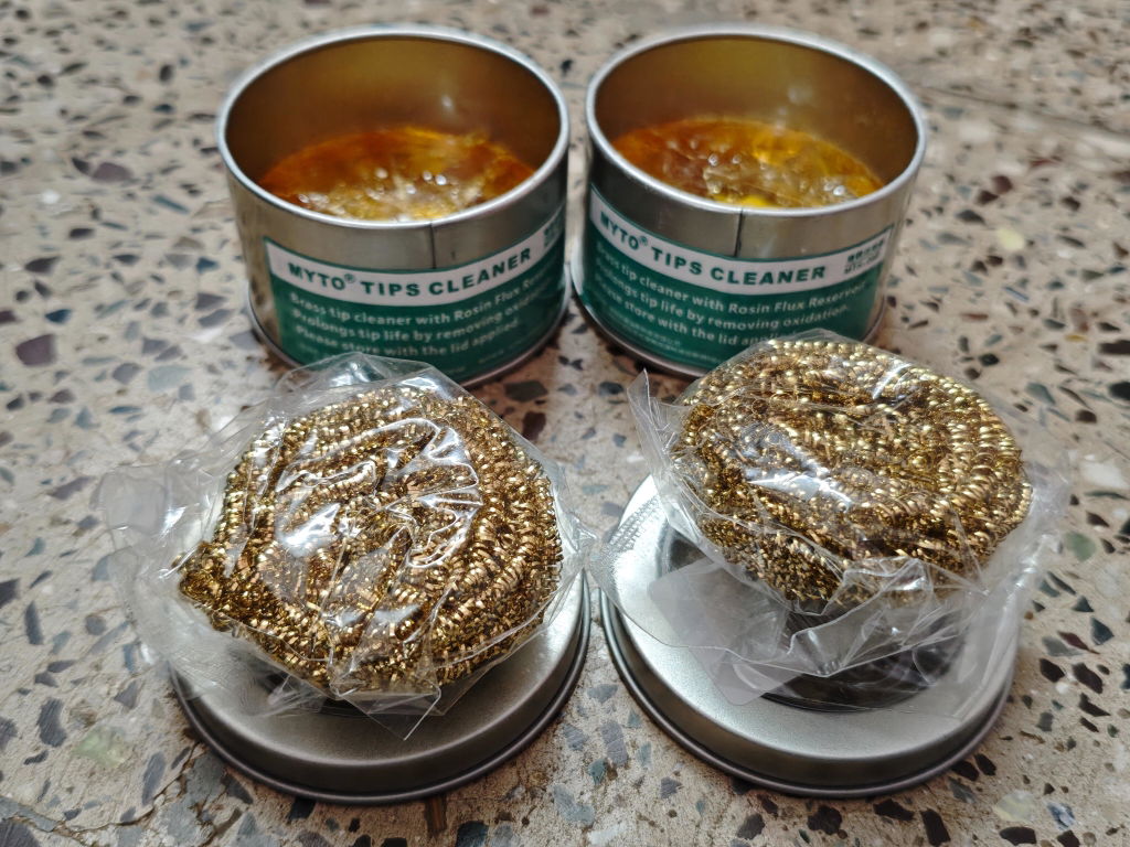
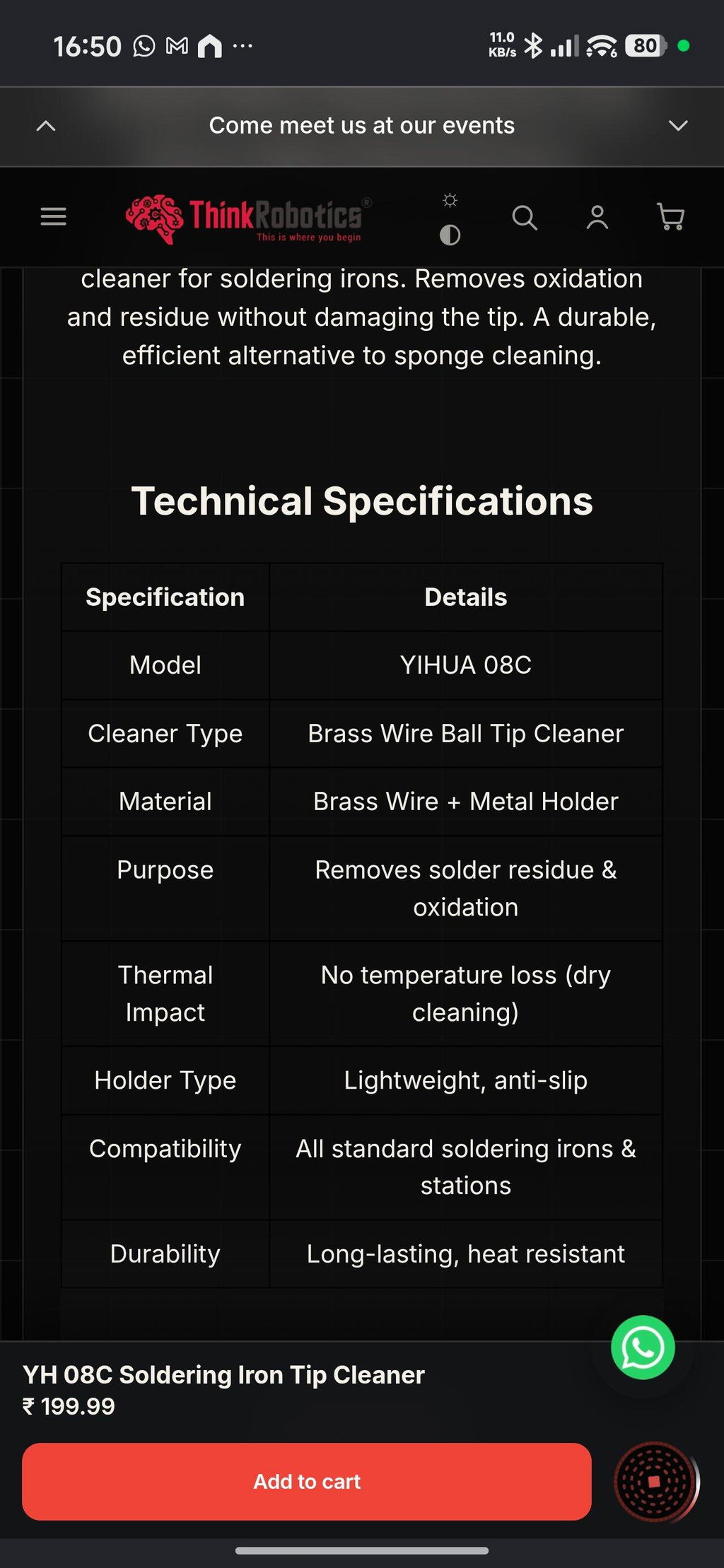
Open tool →Given the fact that this was my first purchase and I made it thinking I was buying genuine Yihua products, this has been a setback. I received a lesser known OEM brand called MYTO and while both the products seem to be similar from appearance, my real contention is the quality and quantity of the brass wool. On top of that not informing the customer about the unavailability of the Yihua product and instead sending a product from a different brand is also antagonising. Henceforth, I might just have to think twice before ordering from ThinkRobotics.
TOF MINIF Range Sensor - UART TOF Time-of-Flight Laser Range Sensor
We are disappointed with our recent order experience. We clearly communicated our requirement for 433 MHz antennas on WhatsApp, but the issue remains unresolved. We have been following up for more than 10 days and are still waiting for a proper refund resolution.
As a regular B2B customer, we expected better support. This experience has affected our trust in ThinkRobotics, and we may have to consider other suppliers for future purchases. We request a fair and prompt refund.
Anodised Aluminium Cup Head Washers (Pack of 10)