Electrical Energy Calculator
Calculate electricity use from power and duration, or constant DC voltage and current. Compare energy use over different operating times in watt-hours, kilowatt-hours and joules.
Open tool
Interactive calculation is unavailable until JavaScript loads. The formulas, worked examples and references below remain available.
Estimate the peak, minimum and average DC voltage and ripple of a half-wave, bridge or center-tap rectifier with a reservoir capacitor, or the capacitor for a ripple target.
Choose the rectifier: full-wave bridge, full-wave center-tap or half-wave.
Choose Ripple from the capacitor, or Capacitor for a ripple target.
Enter the secondary RMS voltage. For a center-tapped winding, enter the voltage of each half. Choose 50 Hz or 60 Hz.
Keep the diode drop at 1.1 V for standard silicon rectifiers at about 1 A, or enter your diode's value. Enter 0 for ideal diodes.
Enter the DC load current, and the capacitor or the ripple target.
Read the ripple or capacitor, peak and minimum voltage and waveform. Copy result copies the labeled values. Reset restores the starting fields.
A rectifier turns the transformer's alternating voltage into pulses of one polarity. The reservoir capacitor charges to the peak of each pulse and supplies the load between them. The peak of a sine is √2 times its RMS value, less the forward drop of each diode the current passes through: one for half-wave and center-tap circuits, two for a bridge.
Between peaks the capacitor discharges into the load. Treating the load as a constant current for the whole gap gives a ripple of the load current divided by the ripple frequency times the capacitance. Full-wave rectifiers recharge twice per line cycle, so their ripple frequency is twice the line frequency and their ripple half that of a half-wave circuit.
The lowest point of the ripple is what a regulator after the rectifier sees, so compare the minimum output with the regulator's input requirement. The estimate holds when the load's RC time is much longer than the ripple period.
The constant-current model ignores the short recharge time at each peak, so it overstates ripple within this idealized model. Choose the next standard capacitor at or above the calculated value, rated above the peak voltage. Allow for line variation and transformer regulation.
Limitations: the tool assumes a sinusoidal supply, an ideal transformer, a fixed diode drop and a constant load current. It does not model transformer regulation, line-voltage tolerance, diode conduction angle, peak and surge currents, peak inverse voltage or the capacitor's ripple-current rating, and suggests no standard capacitor values. It does not convert between RMS, peak and average values of other waveforms. High voltages can be lethal; disconnect power and discharge capacitors before handling a circuit.
Peak input: V_pk = √2 × V_rms.
Peak output: V_pk,out = V_pk - n × V_D; n = 2 for a bridge, 1 for half-wave and center-tap.
Ripple frequency: f_r = f (half-wave); f_r = 2 × f (full-wave).
Ripple: ΔV = I_L ÷ (f_r × C). ΔV in V, I_L in A, C in F.
Capacitor for a target: C = I_L ÷ (f_r × ΔV).
Minimum and average: V_min = V_pk,out - ΔV; V_avg ≈ V_pk,out - ΔV ÷ 2.
12 V rms, 60 Hz, bridge, ideal diodes, 100 mA, 1000 μF: ΔV = 833.333 mV; peak 16.9706 V, minimum 16.1372 V. 0.1 A ÷ (120 Hz × 0.001 F). The MIT 6.101 handout rounds √2 to 1.4 and gets 16.8 V and 0.83 V.
Same, with 1.1 V per diode: Peak output 14.7706 V, minimum 13.9372 V. A bridge has two diode drops in series, which costs 2.2 V here.
12 V rms, 60 Hz, half-wave, 1.1 V, 100 mA, 1000 μF: ΔV = 1.66667 V; minimum 14.2039 V. The capacitor waits a whole line cycle, so the ripple doubles.
9 V rms, 50 Hz, bridge, 1.1 V, 500 mA, 1 V ripple target: C = 5 mF (5000 μF). 0.5 A ÷ (100 Hz × 1 V). Round up; the minimum output is then 9.52792 V.
6 V rms, 60 Hz, half-wave, 1.1 V, 1 A, 100 μF: No valid result. The estimated ripple, 166.667 V, is far larger than the 7.38528 V peak, so the capacitor is too small for 1 A.
MIT OpenCourseWare 6.101: Power Supply Ripple Voltage Calculation
OpenStax University Physics Volume 2: 15.4 Power in an AC Circuit
onsemi 1N4001-1N4007 rectifier data sheet
Available now
Calculate electricity use from power and duration, or constant DC voltage and current. Compare energy use over different operating times in watt-hours, kilowatt-hours and joules.
Open tool →Available now
Add up to 20 resistors in series using Ω, kΩ or MΩ for circuit analysis and electricity calculations, with a diagram and running total.
Open tool →Available now
Convert absolute temperatures between Celsius, Fahrenheit and kelvin.
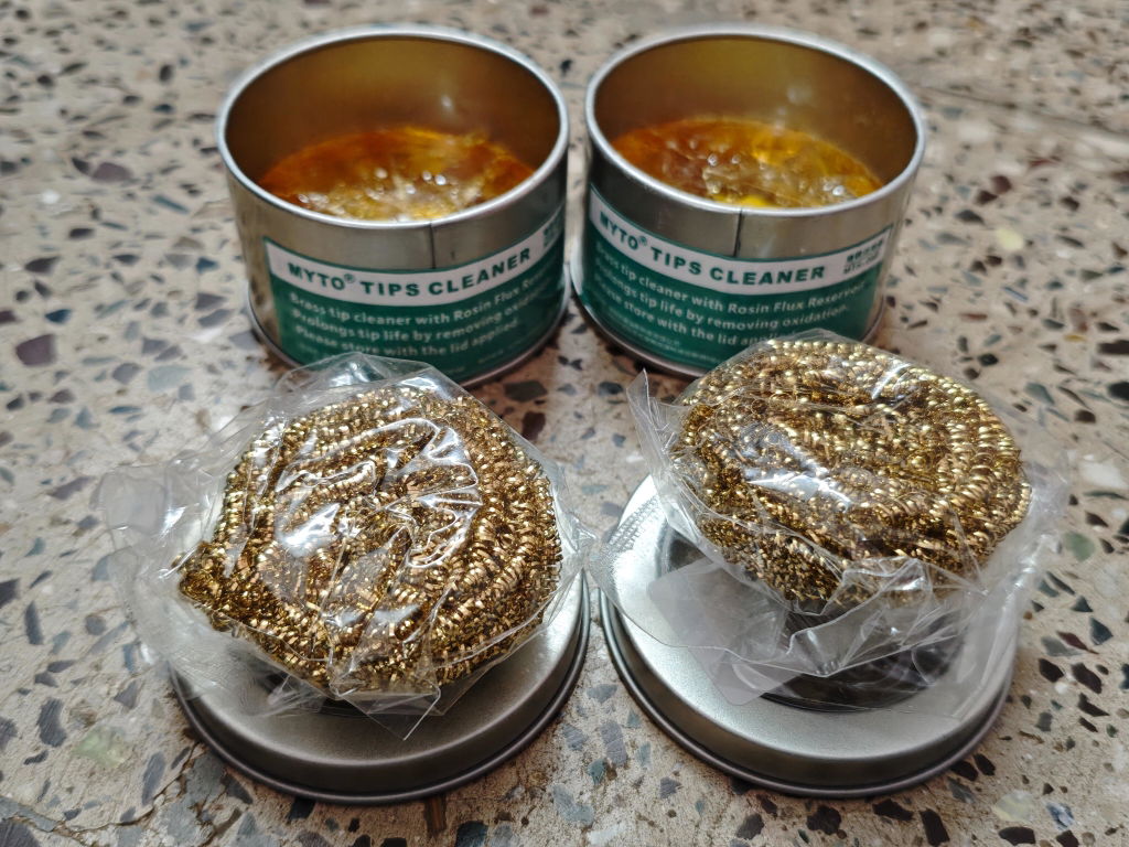
Open tool →Given the fact that this was my first purchase and I made it thinking I was buying genuine Yihua products, this has been a setback. I received a lesser known OEM brand called MYTO and while both the products seem to be similar from appearance, my real contention is the quality and quantity of the brass wool. On top of that not informing the customer about the unavailability of the Yihua product and instead sending a product from a different brand is also antagonising. Henceforth, I might just have to think twice before ordering from ThinkRobotics.
TOF MINIF Range Sensor - UART TOF Time-of-Flight Laser Range Sensor
We are disappointed with our recent order experience. We clearly communicated our requirement for 433 MHz antennas on WhatsApp, but the issue remains unresolved. We have been following up for more than 10 days and are still waiting for a proper refund resolution.
As a regular B2B customer, we expected better support. This experience has affected our trust in ThinkRobotics, and we may have to consider other suppliers for future purchases. We request a fair and prompt refund.
Anodised Aluminium Cup Head Washers (Pack of 10)