Electrical Energy Calculator
Calculate electricity use from power and duration, or constant DC voltage and current. Compare energy use over different operating times in watt-hours, kilowatt-hours and joules.
Open tool
Interactive calculation is unavailable until JavaScript loads. The formulas, worked examples and references below remain available.
Estimate a semiconductor's junction temperature from its power and a thermal path from ambient, case, package top or heat sink, and compare it with the limit.
Choose the thermal path: ambient air and θ_JA, a measured case temperature and θ_JC, a measured package-top temperature and Ψ_JT, or ambient air through a heat sink.
Enter the power the device dissipates in watts.
Enter the reference temperature for that path and the thermal resistances from the data sheet (for a heat sink: θ_JC, the interface θ_CS and the heat sink's θ_SA).
Enter the junction limit from the data sheet, or keep the starting value.
Read the junction temperature, the margin to the limit and the maximum power on this path. Copy result copies labelled values; Reset restores the starting fields.
Heat flows from the junction to the surroundings through thermal resistances, the way current flows through electrical resistances. Each resistance raises the temperature by the power times its value in °C/W, so the junction runs at the reference temperature plus P × θ.
Which θ to use depends on which temperature you know. θ_JA goes with the ambient air, but it is measured on a standard test board where most of the heat leaves through the board, so a different board can change it a lot. θ_JC goes with the case temperature when a heat sink takes the heat from that case surface. Ψ_JT goes with a thermocouple on top of the package and is small because little heat leaves through the top.
With a heat sink, the resistances add in series: junction to case, case to sink through the grease or pad, and sink to ambient. The case and sink temperatures fall out along the way, and dividing the allowed rise by the total gives the most power the path can carry.
Limitations: these are steady-state estimates with constant thermal resistances. Short pulses heat the junction less (they need the transient thermal impedance curve), airflow and neighbouring parts change θ_JA, and data-sheet values have tolerances. Confirm critical designs by measurement, as the application notes advise.
Ambient path: T_J = T_A + P × θ_JA.
Case path: T_J = T_C + P × θ_JC.
Package-top path: T_J = T_T + P × Ψ_JT.
Heat-sink path: T_J = T_A + P × (θ_JC + θ_CS + θ_SA).
Limit: Margin = T_J,max − T_J; P_max = (T_J,max − T_ref) / θ.
100 W, heat sink path: θ_JC 0.8, θ_CS 0.1, θ_SA 0.3 °C/W, 25 °C ambient: T_J 145 °C; case 65 °C; sink 55 °C. 120 °C rise; 5 °C below a 150 °C limit (TI SBOA021).
10 W with a 12 °C/W heat sink and a 0.5 °C/W insulating washer: T_J 158 °C, above a 150 °C limit by 8 °C. The same part reaches only 37 °C on a 0.3 °C/W heat sink with a 0.1 °C/W interface.
1 W, θ_JA 70 °C/W, 65 °C ambient: T_J 135 °C. ROHM 65AN117E's example; P_max at 150 °C is 1.214 W.
2 W, θ_JC 2.6 °C/W, used with the 25 °C ambient: 30.2 °C (wrong). θ_JC must start from the case temperature; with the ambient air use θ_JA (here 40.5 °C/W gives 106 °C).
0 W at 40 °C: T_J 40 °C. With no power the junction sits at the reference temperature.
Texas Instruments SPRA953: Semiconductor and IC Package Thermal Metrics
Texas Instruments SBOA021: Heat Sinking — TO-3 Thermal Model
ROHM 65AN117E: How to Use the Thermal Resistance and Thermal Characteristics Parameters
Available now
Calculate electricity use from power and duration, or constant DC voltage and current. Compare energy use over different operating times in watt-hours, kilowatt-hours and joules.
Open tool →Available now
Add up to 20 resistors in series using Ω, kΩ or MΩ for circuit analysis and electricity calculations, with a diagram and running total.
Open tool →Available now
Convert absolute temperatures between Celsius, Fahrenheit and kelvin.
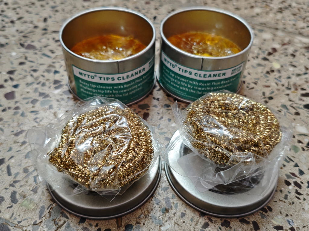
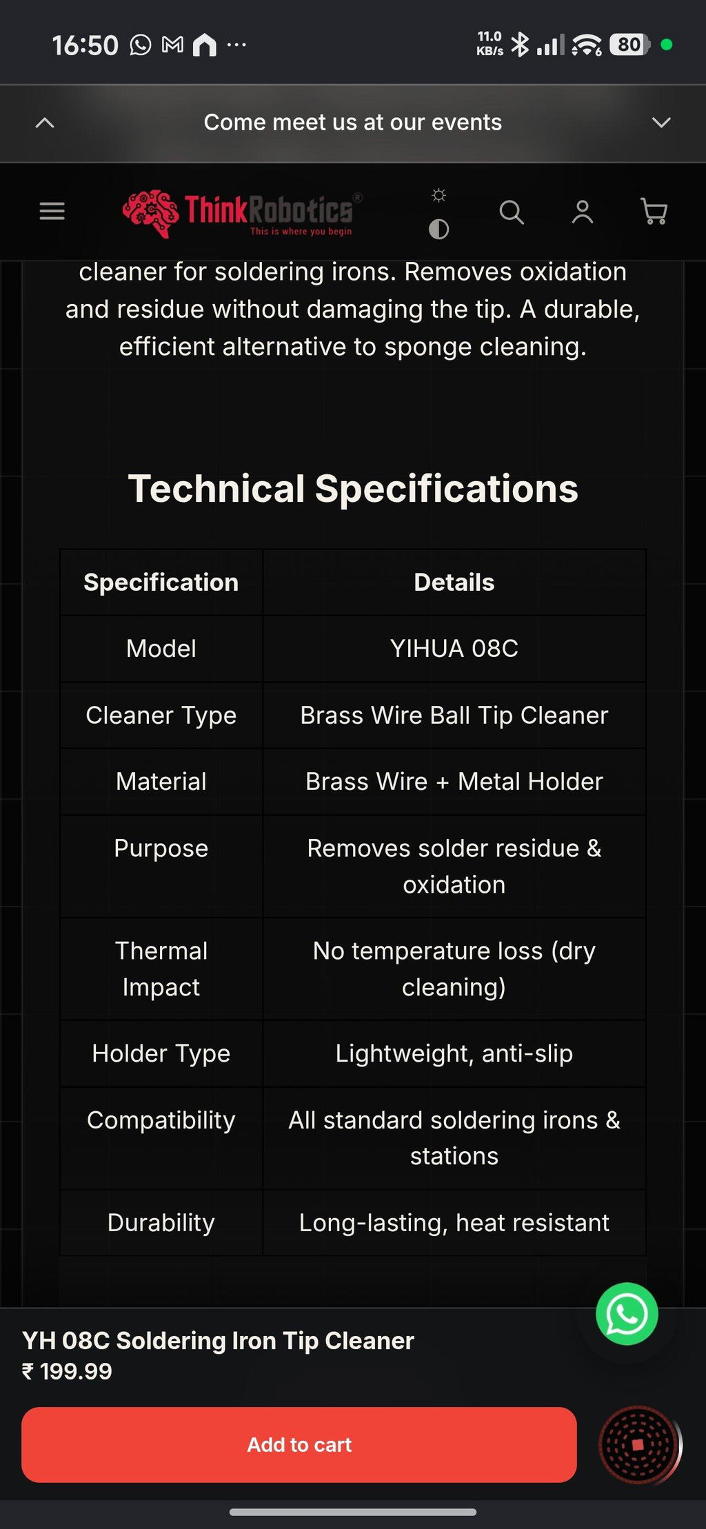
Open tool →Given the fact that this was my first purchase and I made it thinking I was buying genuine Yihua products, this has been a setback. I received a lesser known OEM brand called MYTO and while both the products seem to be similar from appearance, my real contention is the quality and quantity of the brass wool. On top of that not informing the customer about the unavailability of the Yihua product and instead sending a product from a different brand is also antagonising. Henceforth, I might just have to think twice before ordering from ThinkRobotics.
TOF MINIF Range Sensor - UART TOF Time-of-Flight Laser Range Sensor
We are disappointed with our recent order experience. We clearly communicated our requirement for 433 MHz antennas on WhatsApp, but the issue remains unresolved. We have been following up for more than 10 days and are still waiting for a proper refund resolution.
As a regular B2B customer, we expected better support. This experience has affected our trust in ThinkRobotics, and we may have to consider other suppliers for future purchases. We request a fair and prompt refund.
Anodised Aluminium Cup Head Washers (Pack of 10)