Electrical Energy Calculator
Calculate electricity use from power and duration, or constant DC voltage and current. Compare energy use over different operating times in watt-hours, kilowatt-hours and joules.
Open tool
Interactive calculation is unavailable until JavaScript loads. The formulas, worked examples and references below remain available.
Calculate MOSFET conduction loss from RMS drain current and on-resistance corrected to the junction temperature, and compare it with the 25 °C value.
Choose the current waveform: steady DC, switched at a duty cycle, or an RMS current you already know.
Enter the current. For a switched waveform, also enter the duty cycle and peak-to-peak ripple, or enter 0 for a flat top.
Enter the data sheet's maximum R_DS(on) at 25 °C for your gate-drive voltage, then choose mΩ or Ω.
Choose a temperature correction: a multiplier read from the data-sheet curve, or a linear coefficient with a junction temperature.
Read the conduction loss, hot on-resistance and loss calculated with the 25 °C value. Copy the labelled result or reset the inputs.
A fully enhanced MOSFET behaves like a resistor between drain and source. While it conducts, the channel turns I² × R_DS(on) into heat, so loss depends on the square of the current: twice the current gives four times the heat.
For a current that switches on and off, the heat follows the RMS value, not the average. A switch that carries 10 A for half of each period has an RMS current of 7.07 A and half the DC loss. Ripple on the on-state current adds a little more, ΔI² / 12 inside the root.
R_DS(on) rises with junction temperature. Data sheets give it at 25 °C and plot a normalized curve against temperature. Reading that curve at the expected junction temperature and using the maximum rather than the typical value avoids underestimating the heat. Because loss raises the temperature, which raises R_DS(on) again, a final design checks the junction temperature (tool 096) and repeats the calculation until the two agree.
Limitations: this is conduction loss only. Switching transitions, gate drive (tool 111), the body diode and dead time add their own losses. R_DS(on) also depends on gate voltage and drain current. The trapezoid model assumes a constant ramp, a linear coefficient only approximates the curved data-sheet characteristic, and paralleled devices rarely share current exactly. Use the result for comparison and sizing, then confirm critical designs by measurement.
RMS current: I_rms = I_D for DC; I_rms = sqrt(D × (I_D² + ΔI² / 12)) for a switched current with duty cycle D and peak-to-peak ripple ΔI.
Hot on-resistance: R_DS(on),TJ = R_DS(on),25 × k, where k is read from the normalized curve, or k = 1 + α / 100 × (T_J − 25).
Conduction loss: P_cond = I_rms² × R_DS(on),TJ. P in W, I in A, R in Ω.
On-state drop: V_DS(on) = I_D × R_DS(on),TJ.
10 A DC, R_DS(on) 10 mΩ at 25 °C, multiplier 1.5: 1.5 W; R_DS(on) 15 mΩ; 150 mV drop. The 25 °C value would give only 1 W.
10 A on-state current at 50 % duty, 4 A ripple, 10 mΩ and multiplier 1.5: 760 mW; I_rms 7.118 A. Without ripple the RMS current is 7.071 A and the loss is 750 mW.
20 A DC, 5 mΩ, coefficient 0.4 %/°C at T_J 100 °C: 2.6 W; multiplier 1.3. k = 1 + 0.4 / 100 × 75.
30 A DC, 3.3 mΩ typical, junction at the data sheet's 1.7 multiplier: 5.049 W, not 2.97 W. Using the 25 °C value underestimates the heat by 41 %.
10 A for 50 % of each period, 10 mΩ, multiplier 1.5, entered as its 5 A average on the DC setting: 375 mW instead of 750 mW. The average current halves the estimate; heat follows the RMS current, 7.071 A.
ROHM 65AN041E: Notes for Calculating Power Consumption: Static Operation
ROHM 65AN117E: How to Use the Thermal Resistance and Thermal Characteristics Parameters
Available now
Calculate electricity use from power and duration, or constant DC voltage and current. Compare energy use over different operating times in watt-hours, kilowatt-hours and joules.
Open tool →Available now
Add up to 20 resistors in series using Ω, kΩ or MΩ for circuit analysis and electricity calculations, with a diagram and running total.
Open tool →Available now
Convert absolute temperatures between Celsius, Fahrenheit and kelvin.
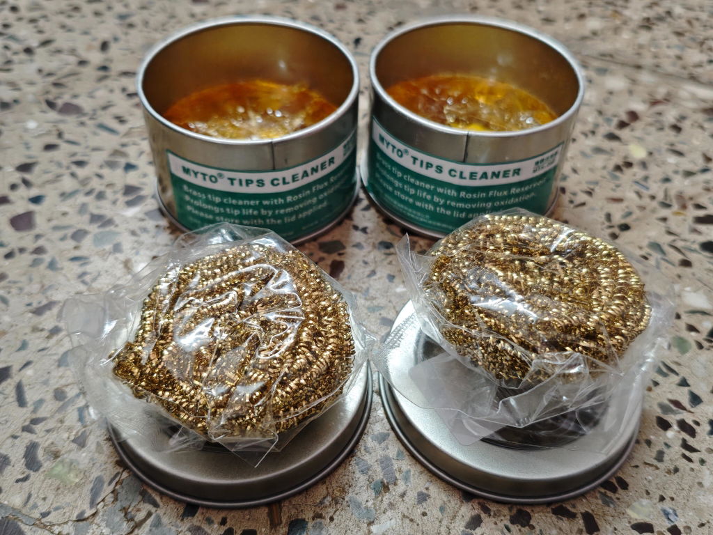
Open tool →Given the fact that this was my first purchase and I made it thinking I was buying genuine Yihua products, this has been a setback. I received a lesser known OEM brand called MYTO and while both the products seem to be similar from appearance, my real contention is the quality and quantity of the brass wool. On top of that not informing the customer about the unavailability of the Yihua product and instead sending a product from a different brand is also antagonising. Henceforth, I might just have to think twice before ordering from ThinkRobotics.
TOF MINIF Range Sensor - UART TOF Time-of-Flight Laser Range Sensor
We are disappointed with our recent order experience. We clearly communicated our requirement for 433 MHz antennas on WhatsApp, but the issue remains unresolved. We have been following up for more than 10 days and are still waiting for a proper refund resolution.
As a regular B2B customer, we expected better support. This experience has affected our trust in ThinkRobotics, and we may have to consider other suppliers for future purchases. We request a fair and prompt refund.
Anodised Aluminium Cup Head Washers (Pack of 10)