Electrical Energy Calculator
Calculate electricity use from power and duration, or constant DC voltage and current. Compare energy use over different operating times in watt-hours, kilowatt-hours and joules.
Open tool
Interactive calculation is unavailable until JavaScript loads. The formulas, worked examples and references below remain available.
Plot the step or natural response of a series RLC circuit, classify its damping and find the overshoot, ringing frequency and settling time.
Choose Step response or Natural response and enter the voltage.
Enter the resistance, inductance and capacitance with their units.
Read the damping class and ζ, then the ringing frequency, overshoot and settling time.
Optionally enter a time to read the capacitor voltage and current then; the graph marks it.
Copy result copies labeled values; Reset restores the starting fields.
A resistor, inductor and capacitor in series form a second-order circuit: L C v'' + R C v' + v = V. Energy moves between the capacitor's electric field and the inductor's magnetic field. The resistor removes some energy on every swing.
Two numbers describe the response. The undamped angular frequency ω0 = 1/√(LC) sets how fast it swings; the damping ratio ζ = (R/2)√(C/L) says how quickly the swings die away. Below ζ = 1 the circuit rings at ω0√(1 − ζ²) and overshoots; at ζ = 1 (R = 2√(L/C)) it rises without overshoot; above 1 it creeps toward the final value.
For a step, the overshoot is e^(−πζ/√(1−ζ²)): 16.3 % at ζ = 0.5 and 4.3 % at ζ = 0.707. Critical damping is not always the fastest to settle: a slightly underdamped circuit can enter the 2 % band sooner, while a heavily overdamped one is slow because of its slow root.
The natural response starts with the capacitor charged and no source. It has the same damping and frequency; the voltage falls toward 0 V and, when underdamped, swings below it.
Limitations: the components are ideal and linear, the source is an ideal step with no resistance, and the circuit starts with no inductor current. Real inductors and capacitors add resistance, self-resonances and nonlinearity, and a real switch has its own resistance and bounce. Use the readout for exact values; the graph is sampled at 181 points.
Circuit: L × C × v'' + R × C × v' + v = V_s. V_s = V for a step, 0 for the natural response.
Frequencies: ω0 = 1 / √(L × C); α = R / (2L); ζ = α / ω0 = (R / 2) × √(C / L); Q = 1 / (2ζ).
Underdamped: v(t) = V_f + x0 × e^(−αt) × (cos(ωd t) + (α / ωd) × sin(ωd t)), ωd = √(ω0² − α²).
Critical: v(t) = V_f + x0 × e^(−αt) × (1 + αt).
Overdamped: v(t) = V_f + x0 × (−s2 × e^(s1 t) + s1 × e^(s2 t)) / (2β), β = √(α² − ω0²), s1 = −ω0² / (α + β), s2 = −(α + β).
Overshoot: M_p = e^(−πζ / √(1 − ζ²)); peak time t_p = π / ωd. x0 = −V for a step, V for the natural response.
Step 5 V; 10 Ω, 1 mH, 10 μF: Underdamped, ζ = 0.5. α = 5000 s⁻¹, ω0 = 10 krad/s. Overshoot 16.3034 % (5.81517 V at 362.76 μs), ringing 1.37832 kHz, within 2 % by 807.635 μs.
Same circuit with 20 Ω: Critically damped, ζ = 1. R = 2√(1 mH / 10 μF) = 20 Ω. No overshoot; within 2 % by 583.392 μs.
Same circuit with 100 Ω: Overdamped, ζ = 5. Roots −1.01021 ks⁻¹ and −98.9898 ks⁻¹. The slow root (time constant 989.898 μs) sets the 3.88266 ms settling time.
Natural response: capacitor at 10 V; 10 Ω, 1 mH, 10 μF; read at 100 μs: 6.597 V, −533.507 mA. The capacitor discharges through the inductor; the current is negative because it flows out of the capacitor.
Step 5 V with R = 0: Undamped: never settles. Boundary: ζ = 0, so the voltage swings between 0 V and 10 V forever (100 % overshoot).
Critical damping guessed as R = √(L/C) = 10 Ω: Underdamped, 16.3 % overshoot. Common mistake: critical damping needs twice that, R = 2√(L/C) = 20 Ω.
OpenStax University Physics Volume 2: RLC series circuits
MIT OpenCourseWare 2.004: Second-order system step response (Lecture 20)
University of Illinois ECE 486: Second order system, overshoot and peak time
Available now
Calculate electricity use from power and duration, or constant DC voltage and current. Compare energy use over different operating times in watt-hours, kilowatt-hours and joules.
Open tool →Available now
Add up to 20 resistors in series using Ω, kΩ or MΩ for circuit analysis and electricity calculations, with a diagram and running total.
Open tool →Available now
Convert absolute temperatures between Celsius, Fahrenheit and kelvin.
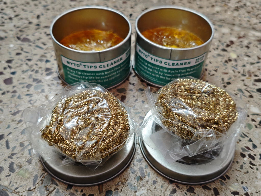
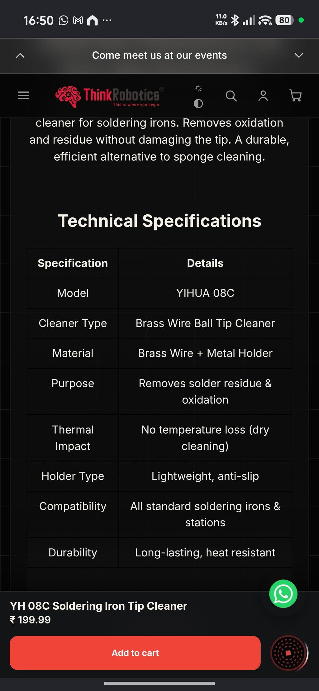
Open tool →Given the fact that this was my first purchase and I made it thinking I was buying genuine Yihua products, this has been a setback. I received a lesser known OEM brand called MYTO and while both the products seem to be similar from appearance, my real contention is the quality and quantity of the brass wool. On top of that not informing the customer about the unavailability of the Yihua product and instead sending a product from a different brand is also antagonising. Henceforth, I might just have to think twice before ordering from ThinkRobotics.
TOF MINIF Range Sensor - UART TOF Time-of-Flight Laser Range Sensor
We are disappointed with our recent order experience. We clearly communicated our requirement for 433 MHz antennas on WhatsApp, but the issue remains unresolved. We have been following up for more than 10 days and are still waiting for a proper refund resolution.
As a regular B2B customer, we expected better support. This experience has affected our trust in ThinkRobotics, and we may have to consider other suppliers for future purchases. We request a fair and prompt refund.
Anodised Aluminium Cup Head Washers (Pack of 10)