
AC and DC
All of us, at some point, would have got a doubt about AC & DC. To put it in simple words, Alternating current (AC) is defined as the flow of charges that change direction periodically, and Direct current (DC) has a unidirectional flow of charges and remains the same as long as terminals connected are not changed.
How do they look?
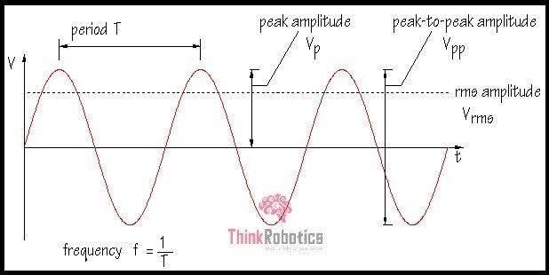
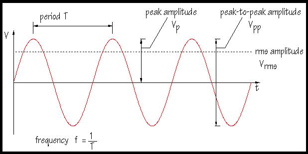
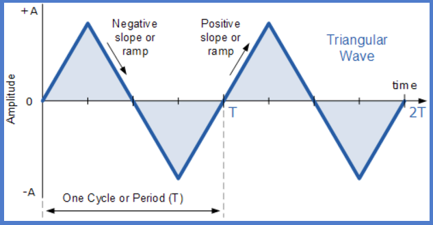
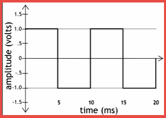
Since AC is alternating in nature, both the voltage and current keeps changing from positive to negative or vice-versa at regular intervals, AC is produced by a specially designed machine called an alternator. This machine works on the electromagnetic induction law of Faraday, which states that ‘when the magnetic flux linking a circuit changes, an electromotive force is induced in the circuit proportional to the flux rate linkage’. The generated AC can be sinusoidal, triangular, or square. This is how an AC waveform looks-


As the name suggests, DC or Direct Currents are one-way, and so they have constant magnitude, ideally. The frequency in the case of DC voltage/currents is zero. The working principle of DC generators is also Faraday’s law of electromagnetic induction. But the internal design and structure are different.

What is it used?
All the residential, commercial, and most of the industrial loads are fed from AC supply. The difference they can have is in terms of phases. That is, residential loads at homes like lighting &heating loads require lesser voltage, so they run on a single phase out of three phases. Whereas, the industrial loads and few times, commercial loads need higher voltage to work, so they use 2 or 3 phases.
Did you know that the energy obtained from solar panels is DC? DC finds its use in many off-grid applications. Be it battery for your car or an aircraft or any other low battery and low current application.
One particular use of DC voltage is in high voltage power transmission. For long-distance transmission over 600 KV, AC transmission is not economical. Instead, DC transmission proves to be much more economical; that’s why used in countries like the USA, China, and even India.
The DC distribution technique has been applied to some domains, such as communication, ships, and rail transit. The corresponding research and standards of DC power supply in these domains are formulated.
AC/DC distribution Network
Many scientific and research institutes have come up with a proposed system of AC/DC distribution network. The basic modules in such a network could be power supply, distribution automation, power source access, and load access.
Though this is still on the theory level, AC/DC distribution network has huge application fields, and that proves to be the accelerating factor here. They find applications in the data centres, electric vehicle charging station, rail transit, and other DC loads requiring medium and low voltage. Other applications like Industrial park, Interconnection of different distribution subareas via DC networking, since it does not involve phase angles, phase voltages, etc. Here is a table stating a few crucial differences between AC & DC.

When it comes to industrial loads par say, which uses about 54% of total generated power runs both on AC and DC supply dependent on the application. Machinery ranging from simple 3 phase Induction Motors to Gear DC motor or Highly efficient BLDC (brushless DC) motor, all of them work essential Interconnection of windings. The arrangement of these windings determines the type of machine and the output of the device.
Here’s an overview of these necessary arrangements, namely SERIES and PARALLEL connection.
Series & Parallel:
Passive components such as resistors, inductors, capacitors are an inseparable part of electrical /electronic circuits. All these are two-terminal devices. The orientation or pattern in which they are connected makes a significant impact on the circuit. From a fundamental point of view, they can be connected in series or parallel or both.
This massive impact is in terms of equivalent current, equivalent voltage, and equal power.
When in Series-
Connecting components in series means connecting them next to each other or more precisely connecting positive terminal to negative terminal of next components.

For example, in the above fig, resistors are connected in series (resistors are bi-directional). The current ‘I’ passing via all the components is the same, so current in series remains constant and is the same via all resistors. But the Voltage here is not the same and depends on the magnitude of the component. In this case, the resistances of all the resistors are different. From Ohm’s law, we know that Voltage is directly proportional to Resistance.
Thus, Voltages in series gets added up.
Batteries in series are usually connected to increase the total Voltage since in series voltage gets added up. When batteries are connected in series, they are generally of the same voltage rating and same capacity.
For, Vbattery1 = Vbattery2 = Vbattery3 = Vbattery n
So equivalent voltage in batteries ( Veq ) = Vbattery1 + Vbattery2 + Vbattery3 + ……..+ Vbattery n = n* Vbattery1
By doing so, the maximum capacity of all the batteries can be used. In case all the batteries are not the same, then the Equivalent voltage does not result in the number of battery life voltage of each, and the maximum capacity of these is not exploited.
When solar modules are connected in series, a similar rule is applied. Voltage sums up to give higher Voltage, and since the current passing via all the modules is the same, it remains constant.

Fig 6: Solar modules in series
When solar modules/panels and batteries connected in series have the same voltage rating and varied current rating, then the current, which passes via all the panels/batteries, is the smallest of all the current. This results in reduced power output ( P = V * I ) and damages the panels/ batteries a lot.
When in Parallel:
When components are connected in parallel, their similar terminals are connected. That is, positive terminals of all (similar) components together and negative terminals together.

Fig 7: Parallel connection of resistors
As seen in the above figure, the source splits to supply the resistors and voltage remains constant.
So, current in parallel circuit gets added up and voltage across every parallel connection remains same.
When batteries are connected in parallel capacity in Ah and runtime increases while the voltage remains the same. Even here it is recommended to connect batteries of similar ratings.
Thus, amperage or capacity in Ah gets added up
Capacity battery 1 = Capacity battery 2 = Capacity battery 3= Capacity battery n
So, Capacity eq = Capacity battery 1 + Capacity battery 2 + Capacitybattery3 +………+ Capacity battery n
When solar panels are connected in parallel similar changes takes place.
Voltage across all modules remains same when similar modules/panels are used and the current via each of them sums up to give total or equivalent current.

Fig 8: Solar modules in parallel
Above shown is the simple series and simple parallel connection of components. Practically, 2 or more components are first connected in parallel and such sets can be connected in series to get desired specification, which makes it quite complex.
Sources:
- elprocus.com/main-difference-between-ac-and-dc-currents/
- sinovoltaics.com/learning-center/basics/direct-current-dc-power-definition-and-applications/
- hespv.ca/wp/wp-content/uploads/2014/10/seriesDiagram_updated.jpg
- hespv.ca/wp/wp-content/uploads/2014/10/parallelDiagram_updated.jpg
- “Research on the classic power supply modes of AC/DC distribution network” by Shigong Jiang,Weihong Yang,Yunfei Wang&Hongjun Li published in May 2017, JICEE
- images.app.goo.gl/SSLdeZs9MFVpLWv68
- images.app.goo.gl/5obh72xZBxUBXheG8
- elprocus.com/main-difference-between-ac-and-dc-currents/
- elprocus.com/wp-content/uploads/2016/09/RMS-Sine-Waveform.png
- elprocus.com/wp-content/uploads/2016/09/Trangle-Waveform.png
- elprocus.com/wp-content/uploads/2016/09/Square-Waveform.png
- images.app.goo.gl/Tw47viAfskR2BR3SA
- elprocus.com/main-difference-between-ac-and-dc-currents/