Industrial ESP32-S3 Control Board With RS485 & CAN Interfaces
Based on ESP32-S3, Supports Wi-Fi / Bluetooth, Onboard RS485 & CAN interfaces
Built-in protection circuits such as power isolation and optocoupler isolation, Safe & Stable & Reliable

Features
| Based on ESP32-S3 microcontroller with Xtensa 32-bit LX7 dual-core processor, capable of running at 240 MHz |
Integrated 2.4GHz Wi-Fi and Bluetooth 5 (LE) dual-mode wireless communication, with superior RF performance
|
Onboard isolated RS485 interface, for connecting to various RS485 Modbus industrial modules or sensors
|
Onboard isolated CAN interface for easy access to various CAN devices
|
Onboard pin header for connecting external devices
|
Onboard USB Type-C port for power supply, firmware downloading and debugging
|
Onboard power supply screw terminal, supports 7~36V wide voltage input, suitable for industrial applications
|
Onboard RTC chip, supports scheduled tasks
|
Onboard digital isolation to prevent interference from external signal
|
Onboard unibody power supply isolation, providing stable isolated voltage, no extra power supply is required for the isolated terminal
|
Onboard RS485 TX/RX indicators and CAN indicator for monitoring the operating status of the module
|
Rail-mounted protective case, easy to install, safe to use
|
Specifications
| Microcontroller |
ESP32-S3 (Default module: ESP32-S3R8, customizable for other modules) |
| Wireless communication |
2.4GHz WiFi (802.11 b/g/n), Bluetooth 5 (LE) |
| USB |
Connector |
USB Type-C |
| Power supply |
5V |
| Functions |
Power supply, USB communication, firmware downloading, etc. |
| Isolated RS485 |
Connector |
Screw terminal |
| Direction control |
Automatically controlled via main controller hardware flow settings |
| Protection |
TVS diode, surge protection & ESD protection |
| Resistor |
Onboard reserved 120R matching resistor, NC by default, enabled via jumper |
| ISOLATED CAN |
Connector |
Screw terminal |
| Direction control |
Hardware automatic control |
| Protection |
TVS diode, surge protection & ESD protection |
| Resistor |
Onboard reserved 120R matching resistor, NC by default, enabled via jumper |
| LED Indicators |
PWR indicator |
Red power indicator, lights up when there is USB connection and voltage is detected |
| Relay indicator |
Lights up when the Normally Open (NO) is closed |
| RS485 indicator |
lights up green when the RS485 port sends data
lights up blue when the RS485 port receives data |
| Power supply screw terminal |
Voltage range |
7V ~ 36V |
| Appearance |
Enclosure |
Rail-mount protective case |
| Dimensions |
91.6 × 23.3 × 58.7 (mm) |
Based on ESP32-S3, Designed for AIoT Market
Equipped with Xtensa 32-bit LX7 dual-core processor, capable of running at 240 MHz, with Powerful AI Computing Performance and Security Encryption Mechanism; Integrated 2.4GHz Wi-Fi and Bluetooth 5 (LE) dual-mode wireless communication

Onboard Multiple Isolation Protection Circuits
Multiple protections, more safe and reliable

Application Scenario
Allows users to access the relevant webpage via a mobile phone or PC browser to control the device and send data

Supports Arduino Development
Comprehensive SDK, Dev Resources, And Tutorials To Help You Easily Get Started

Application Example
Provides demo code for IoT connectivity by integrating communication interfaces with a web page, enabling data visualization services

Interface Description

| Top Terminal Block Description |
Bottom Terminal Block Description |
| Power Supply Terminal |
Power positive: DC 7V ~ 36V |
RS485 Terminal |
A+ signal pin |
| Power negative |
B- signal pin |
| Type-C |
for power supply, firmware download, and USB communication |
CAN Terminal |
H signal pin |
| SH1.0 |
GND |
Ground (GND) |
L signal pin |
| 3V3 |
3.3V power output |
|
|
| GPIO2 |
ESP32-S3 IO pin |
|
|
| GPIO1 |
ESP32-S3 IO pin |
|
|

What's On Board

1. ESP32-S3
up to 240MHz operating frequency, with 2.4GHz WiFi and BLE
|
12. LED indicators
PWR: Power indicator
RS485: lights up green when the RS485 port sends data; lights up blue when the RS485 port receives data
CAN: blinks during data transmission
|
2. DC-DC power module
supports up to 3.3V 2A output |
13. ESP32 BOOT button
|
3. Pin header (2.0mm pitch)
for connecting to other functional modules |
14. ESP32 RESET button
|
4. Power supply screw terminal
supports DC 7~36V wide voltage input
|
15. Power supply isolation
Provides stable isolated voltage, no extra power supply is required for the isolated terminal
|
5. USB Type-C port
for module power supply, firmware downloading and USB communication |
16. RS485 matching resistor
Onboard reserved 120R matching resistor, enabled via jumper |
6. RTC battery header
for connecting rechargeable RTC battery (SH1.0) |
17. CAN matching resistor
Onboard reserved 120R matching resistor, enabled via jumper
|
| 7. Onboard ceramic antenna |
18. RS485 & CAN communication terminal
for connecting external RS485 and CAN devices
|
8. IPEX 1 connector
for connecting external antenna, enabled via resoldering an onboard resistor |
19. PCF85063 RTC chip
|
9. 16MB Flash
|
20. DC-DC power chip
|
10. Digital isolation
prevents interference from external signal
|
21. ME6217C33M5G
Low dropout regulator, 800mA output (Max.)
|
11. CAN transceiver chip
|
22. RS485 transceiver chip
|
|
23. TVS diode
Effectively suppresses surge voltage and transient spike voltage in the circuit
|
Enclosure Design
Protection Enclosure With Rail-Mount Support, Easy To Install, Safe To Use

Outline Dimensions

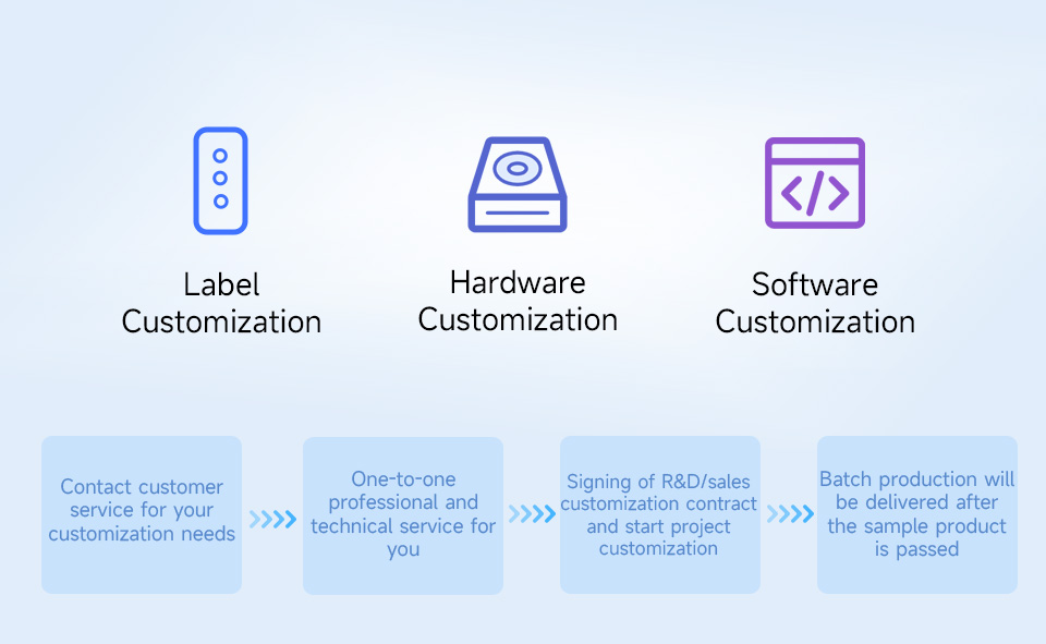
Support Batch Customization
Support software and hardware customization
Including hardware interface, LOGO, label, case and web page, etc.
Resources & Services
Wiki: www.waveshare.com/wiki/ESP32-S3-RS485-CAN
Package Content
Weight: 0.06 kg
ESP32-S3-RS485-CAN x1
SH1.0 4PIN cable ~150mm x1
Screwdriver x1


