


The HCSR04 ultrasonic sensor can sense the distance between itself and the object in front of it. It uses the formula d=(v*t)/2 to calculate the distance. We can display the output on an LED matrix, rather than viewing it on the serial monitor. This makes the project more portable and we can avoid having it attached to a computer for just viewing the distance. Here’s a tutorial on how to use the LED matrix.
This tutorial will involve not only interfacing the ultrasonic sensor with Arduino, but also displaying the output on an 8x32 LED matrix (or 4 8x8 LED matrices)
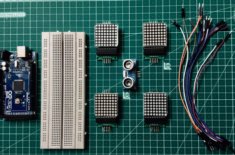
Components required
Basic working of the project
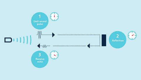
The ultrasonic sensor emits a pulse. This pulse strikes the object and returns back to the sensor. Henceforth the overall distance travelled is 2 x D, considering that the distance one way is D. The velocity of sound in air is 340 m/s. Now once we obtain the total time taken, we can insert all three parameters into the equation v=2D/t. Rearranging the equation, it becomes D=v*t/2.
Henceforth using this formula, the distance is calculated.
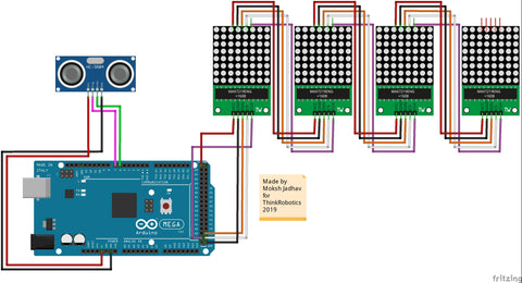
The information is then processed by the Arduino, and then displayed on the 8x32 LED matrix, which is connected to the Arduino board by I2C bus. I have used an Arduino Mega henceforth the MOSI pin is 51, SCK pin is 52 and SS pin is 53. Find out your boards I2C pins before wiring.
Connections
The Echo pin of the ultrasonic sensor goes to digital pin 6 of the arduino and the Trig pin goes to digital pin 7.
To daisy chain the matrices, connect the dout pin of the first matrix to the din of second, CLK to CLK, CS to CS, VCC to VCC, and GND to GND.
I have already mentioned where to connect the DIN CLK and CS pin of the matrix in the working part.
Here’s a schematic to show you how the wiring looks like. I haven’t used a breadboard, but feel free to use one if you want to work with a breadboard.
Libraries and code.
Once you’re done wiring, install the adafruit GFX library and the MAX72xx Panel library. No need to install the SPI library as it is already included in the Arduino IDE by default.
If you find any problem in the order of the matrices, change it in the code.
Author: Moksh Jadhav